capacitor B43510-A5228-M7 2200uf 450v original new | Бытовая техника
5 793,69 руб.


Новое поступление
Характеристики
*Текущая стоимость уже могла изменится. Что бы узнать актуальную цену и проверить наличие товара, нажмите "Добавить в корзину"
| Месяц | Минимальная цена | Макс. стоимость | Цена |
|---|---|---|---|
| Sep-18-2025 | 0.85 руб. | 0.3 руб. | 0 руб. |
| Aug-18-2025 | 0.84 руб. | 0.79 руб. | 0 руб. |
| Jul-18-2025 | 0.70 руб. | 0.91 руб. | 0 руб. |
| Jun-18-2025 | 0.30 руб. | 0.54 руб. | 0 руб. |
| May-18-2025 | 0.1 руб. | 0.17 руб. | 0 руб. |
| Apr-18-2025 | 0.79 руб. | 0.47 руб. | 0 руб. |
| Mar-18-2025 | 0.71 руб. | 0.70 руб. | 0 руб. |
| Feb-18-2025 | 0.71 руб. | 0.60 руб. | 0 руб. |
| Jan-18-2025 | 0.16 руб. | 0.13 руб. | 0 руб. |
Описание товара


modname=ckeditor

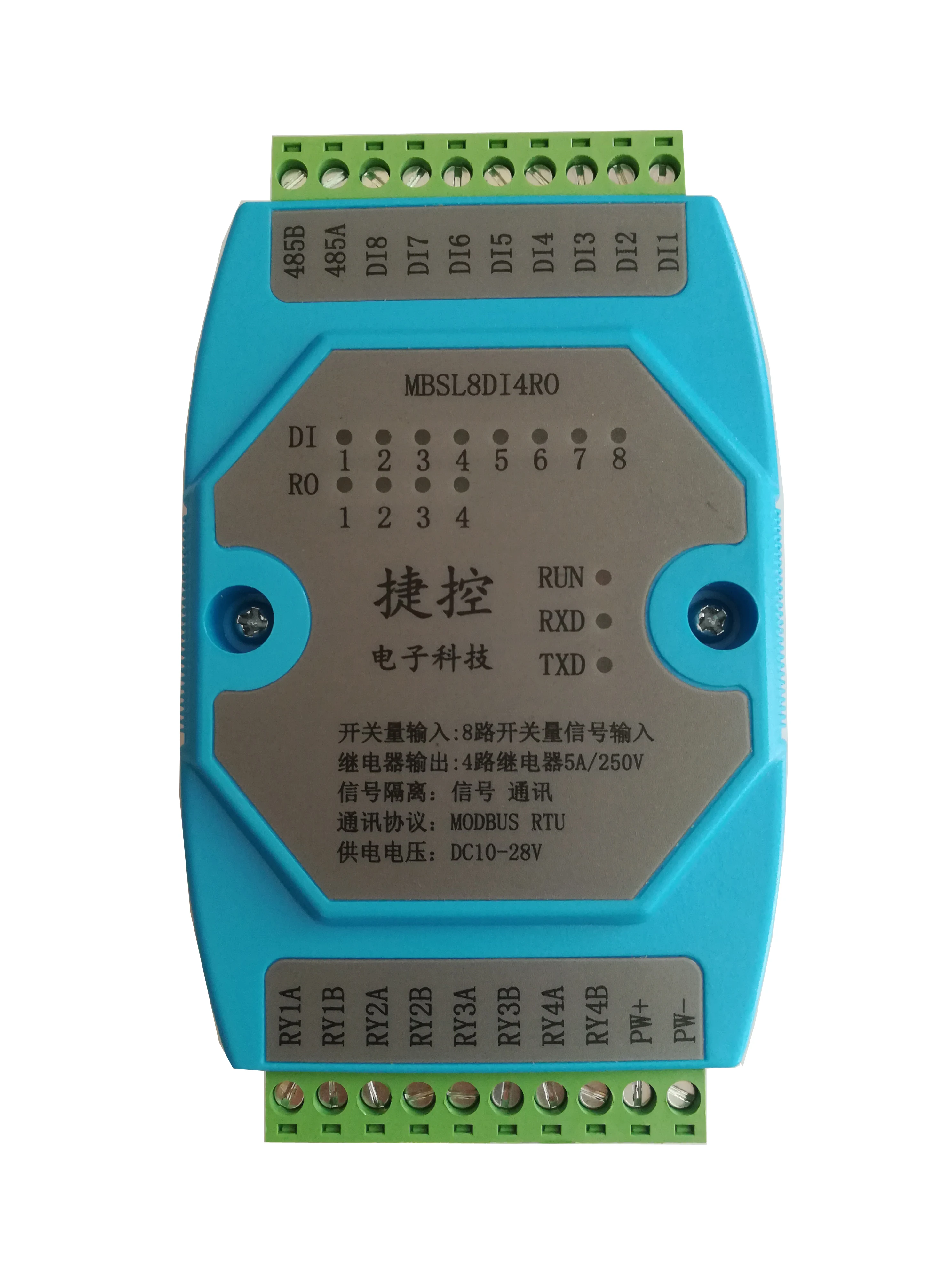
Chapter Product introduction
One、Product overview
MBSL8DI4ROModule is8Road Digital Quantity Isolated Input、4Isolated Output Module of Road Relay,By isolationRS485Interface output。Modules adopt standardModbus RTUcommunication,It can be directly adapted to various upper computer configuration software.、PLC、DCSetc.。Module power supply、RS485Communication electrical signals are isolated from each other,Effectively suppress all kinds of serial mode and common mode interference,At the same time, it ensures the stability of the module.、Reliable work。
1、UseRS485 MODBUS RTUStandard communication,Configurable Software with Upper Computer、PLC、Industrial touch screen networking、With Communication Status Indicator。
2、Industrial standard:signal control、Power Supply、RS485Electrical signals such as communication are isolated from each other。
3、Lightning Protection for Communication Circuit、Anti-interference design、Polarity Protection of Power Supply。
4、RS485Overvoltage and Overcurrent Double Protection for Communication Signal Output Interface。
5、It can be widely used in signal acquisition and control of industrial field equipment.。
6、Output disconnection protection:When the module slave station detects that the master station has exceeded the set time, it does not send data.,Automatic reset output,Protecting the safety of field equipment。Default uninterrupted network protection function,Options can be set
7、Communication format can be set by software。
Two、Main Technical Indicators
| term order |
Technical index |
| Signal input/output |
1、Input channel:8Road Digital Quantity Input 2、Output channel:4Circuit relay output 3、Load capacity:Resistive load250V/2A inductive load250V/1A 4、Relay coil and contact isolation voltage:2000V |
| Communication output |
1.Communication protocol:MODBUS-RTU 2.Interface type:quarantineRS485communication,Overvoltage and Overcurrent Double Protection for Output Interface 3.baud rate: 4800bps、9600bps、19200bps、38400bps、57600bps 4.Parity bit:No check、Parity check、Odd parity check 5.Setting mode:Module address、baud rate、Check bits can be set by software6.Communication distance:@9600bps 1200rice |
| Module size and installation method |
1、 Installation mode:standardDINGuide rail installation or screw installation 2、 Outline size:125×73×35mm |
| work environment |
temperature:-10~+60℃ humidity:35~85%(No condensation) |
| Working power supply |
1.Power supply voltage:10V~30VWide range power supply,Polarity Protection with Power Supply 2.Power consumption:less than3W |
Three、Interface definition
| Terminal name |
say bright |
Terminal name |
say bright |
| PW+ |
External power input front end |
485A |
RS485signalA+ |
| PW- |
Negative input end of external power supply |
485B |
RS485signalB- |
| DI1 |
Digital Input Channel1 |
RY1A |
Relay Output Channel1 |
| DI2 |
Digital Input Channel2 |
RY1B |
|
| DI3 |
Digital Input Channel3 |
RY2A |
Relay Output Channel2 |
| DI4 |
Digital Input Channel4 |
RY2B |
|
| DI5 |
Digital Input Channel5 |
RY3A |
Relay Output Channel3 |
| DI6 |
Digital Input Channel6 |
RY3B |
|
| DI7 |
Digital Input Channel7 |
RY4A |
Relay Output Channel4 |
| DI8 |
Digital Input Channel8 |
RY4B |
Four、 Schematic diagram of module wiring

Five、Communication instructions
1、Communication parameter description(Factory value): 9600,N,8,1
| parameter |
Explain |
| 9600 |
baud rate |
| N(No check) |
Parity bit |
| 8 |
Data bits |
| 1 |
Stop bit |

\
\
The second chapter ModbusRegister and Communication Protocol Description
One. Modular supportedMODBUSFunction code and address range
1.Modular supportedMODBUSFunction code
| Register type |
Address range |
Function code |
Function Code Description |
exercise do |
|
Output Coil Register |
00001-00004 |
0x01H |
Read multiple coil registers |
Read the value of one or more coil registers |
| 0x05H |
Write a coil register |
Write the value of a coil register |
||
| 0x0FH |
Write one or more coil registers |
Write the value of one or more coil registers |
||
| Keep Register |
40001-40016 |
0x03H |
Read multiple hold registers |
Read the value of one or more holding registers |
| 0x 06H |
Write a single hold register |
Write a data to the hold register |
||
| 0x 10H |
Write multiple hold registers |
Write one or more data to the hold register |
||
| Input Digital Quantity |
10001-10008 |
0x0H |
Read input discrete quantity |
Discrete Input Register |
Смотрите так же другие товары: